
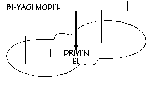
When modeled as vertical quarter-wave monopoles against an infinite ground plane, the five element Bi-Yagi radiates close to a figure eight pattern. Consisting of simply one one-inch diameter driven element matched omega fashion, with two directors at each side, operation is pretty straightforward. Gain is near four DBd in TWO directions. It can be thought of as simply a half, or single ended Yagi operating against a ground plane, turned horizontal.
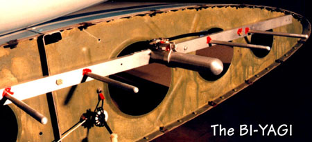
 A conventional Yagi-Uda array operates similar to a phased driven array, with directional cancellation or reinforcement achieved by a combination of element spacing, element current ratios and phases. The only difference is, with a parasitic array, currents are induced, and phase is controlled by tuning parasitic elements reactively above or below resonance to generate the current phase lead or lag. The unit was mounted inside the fiberglass wingtip, which makes a nice radome.
Based upon on-air reports during flight testing it was observed that indeed
a fore-aft pattern appears, but nulls at the 90 degree points seem asymmetrical,
as expected with wingtip mounting. The antenna is fed directly with 20 feet
of LMR coaxial cable. Normal operation is horizontally polarized - occasional
pilot-induced vertical polarization is limited by co-pilot complaints.