I use an old favorite multiband antenna on forty and eighty meters - the center-fed inverted V dipole, fed with true open wire feedline -sometimes known as "tuned feeders". Nothing new about this, except it seems to have been forgotten by many. One rule-of-thumb with antennas is that one which is optimized for one band, is superior to a multiband antenna, all other things being equal. I believe this antenna comes the closest to upsetting that rule. Perfect VSWR is not essential for good efficiency, but RF power amplifiers can get upset with much mismatch - this antenna yields perfect VSWR anywhere on the bands. And it is very efficient due to the ultra-low loss inherent to open wire line - the only significant loss is in the impedance matching network - my Johnson KW matchbox. I need to measure this loss, but I know it does not cause any noticeable component heating after five minutes of a kilowatt through it.
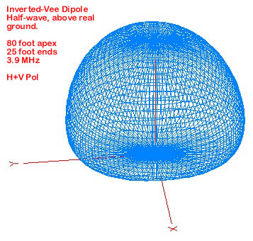
A 3D pattern of aggregate horizontal and vertical polarized radiation of the inverted vee over real ground is shown above. Amazingly, according to the EZnec model, it approaches being omni directional.
Sidebar: This antenna is very different from antennas fed with coax which require a tuner in the shack. If you are after efficiency, coax should never be "tuned" (except in the case of minor mismatch, for instance changing a 3.0 VSWR to 1:1 - the idea being that at 3:1 or less with good rg-8 or better coax on the lower frequencies, the increased loss is not too bad) Trying to tune out more mismatch, particularly with long coax runs is asking for low efficiency. Rule of thumb - if the antenna produces more than 3:1 VSWR, and you want to feed it with coax, match it to 50 ohms with a network at the antenna, not in the shack.
Many hams seem to believe that "resonant" antennas are fundamentally superior to those requiring a matching network. This mistaken belief may stem from the correct idea that using a transmatch on non-resonant coax-fed antennas may please the transmitter, but will radiate poorly. The important difference is that most coaxial cable available to hams works well only when operated close to it's characteristic 50 ohm impedance - losses rise rapidly as the load departs from 50 ohms. The coax actually converts part of your RF power to heat - instead of transferring it to the antenna.
AM broadcast stations are designed to be very efficient - and almost invariably use a non-resonant vertical (tower) fed thru a low loss matching network with coaxial cable. (and 120 radials) BUT, the matching network is at the antenna - so the 50 ohm coax operates at 50 ohms. Typical feed efficiency is on the order of 98% for a single tower station fed with 100 feet of 7/8" inch line through a Tee network at the antenna base.
On the other hand, a well -designed open-wire line can operate with tremendous SWR and still introduce less loss than even well-matched 50 ohm coax over long runs.
Balanced line feeds a balanced load!
We've all seen balanced line feeding off-center fed antennas in the old handbooks - but remember, "single-wire" fed antennas were also used. Feedline radiation wasn't thought about much.
For balanced line to function correctly, (not radiate) it must maintain equal and opposite current in each conductor. In order to do this, the load (antenna) must be balanced with respect to ground and other conductors.
IF the load or source is unbalanced, the currents are unequal, and the line will radiate - a normally undesirable condition - the line radiates energy all the way down to the shack, and into it, causing RF "hot" surfaces and RF in audio and computers.
For the antenna to be balanced, it must be very close to symmetrical in all respects - length and height above ground - think ideal dipole.
An unbalanced antenna can be fed through a balun, but these can introduce significant losses when operated outside their design impedance.
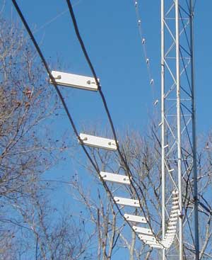
Above:
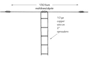
A balanced antenna fed with balanced line.
Although one does not need a 1:1 SWR to achieve good transmit efficiency, the transmitter (3cx800s in my case) may operate better with low VSWR. Particularly on 75 meters, getting a good match across the band can be impossible with a conventional half wave dipole fed with coax. For years the handbook has shown the 130 foot center fed "doublet", using open wire line to be a recommended multiband antenna. I think that if you can deal with the open wire line routing issues, and use an efficient matching network (tuner) it may well be the very best multiband antenna. Balance is important for this type of transmission line to work as intended - each side must have the same current flow.
My configuration
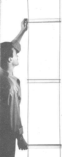
is inverted-vee style with the apex at 80 feet, the ends about 25
feet high. When
I constructed it, I used a capacitance meter from each side to ground
while adjusting end heights to get the same C with respect to ground.
In simple terms, true open wire line (sometimes called tuned feeders) has lower loss for two reasons:
1. The range of average impedances it operates at is generally much higher, with more voltage and less current. The reduced current lessens the ohmic losses in the skin-effect surface of the conductors. This tradeoff places more stress on the insulating materials, which must withstand more voltage without arc-over and must not have much leakage resistance between conductors. If you are a student of the Smith chart, you can see that even a 50 ohm load is transformed into a significantly higher impedance, when using a 400 ohm line.
2. The greatest portion of insulating material in a true open-wire line is air, which has a dielectric constant of 1.0, and is a near lossless insulator. The conductor spacing is sufficient to permit many kilovolts, and the solid spreader insulators can be made of very low loss dielectric materials, glazed steatite being traditional. Spreaders made from 3/8" Teflon rod would probably be optimal in terms of losses.
For you diehards who really prefer coaxial cable, and want to use a tuner in the shack to solve high VSWR, there is a low-loss solution: Click here to see the high performace coax.
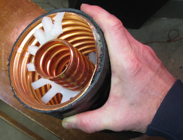
From Terman, Radio Engineering, 2nd ed.
p 700:
"The losses in a properly constructed line can be made very small. Thus
by combining [equation references ...] it is found that a two wire line
made from No. 4 copper wire and having a characteristic impedance of 600 ohms
introduces an attenuation of 0.24 db per thousand feet at 10 mc."
He continues:
"A two wire transmission line radiates very little energy because the close proximity
of the two conductors carrying current in opposite directions very nearly
cancels the radiated field. Analysis shows that in the case of a perfectly
balanced two-wire line the total radiation, including that of the terminal connections,
is twice the radiation that would be obtained from an elementary antenna
having a length equal to the line spacing ... " [not much radiation]
From an ARRL technical advisor and author of the great book "Reflections" ...
"As far as I know, the only feedline materials available for hams are coax, twin-lead, and window line. We know the tremendous advantage window line gives us over coax for using a dipole over all bands, where coax is limited to fundamental and odd harmonics. But the loss due to line attenuation with window line is still much greater than open-wire line separated with spreaders spaced from two to four inches apart."
Walt, W3DU [ from the "AMfone" internet forum]
If however, one wants the ultimate HF line (or is simply enamored with nostalgia) one constructs one's own line. I used 10 gauge copper wire spaced 2 inches apart (radiation is negligible, but lets minimize it with minimal spacing) with ceramic steatite (yes, they are still made) spacers. Its characteristic impedance is about 440 ohms - this value is not critical - even though the line will operate with high SWR (on 75 meters the load will be near 70 ohms), the matchbox presents a near perfect match to the transmitter. Due to the low dielectric losses, line loss remains very low.
Click here to see how open wire line compares according to the ARRL transmission lines loss chart. (From the ARRL antenna Handbook, 17th edition)
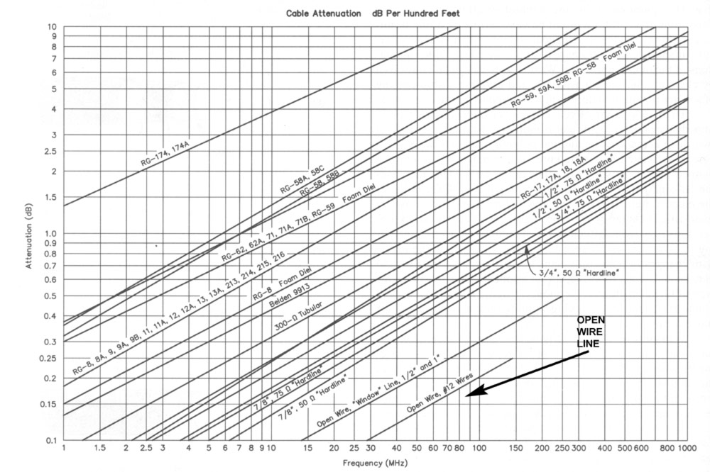
In 1935, Collins published a variation of this system - this pdf presentation over-complicates it a bit, but it's interesting nonetheless.
 The
T
The
T The graph at left shows the impedance relationship to wire spacing. Use spacing between the wires (center to center in inches), divided by the wire diameter shown.
As an example, for my 10 gauge line spaced 2 inches (2 / .101 = a ratio of 19.8) = 441 ohms.
How critical is this? Not very, because the intent of open-wire feeders is to operate the line with VSWR, and match it to 50 ohms near the transmitter. So the line impedance does not have to match either the load or the transmitter. The controlling factor is the tradeoff between amount of radiation and line loss - closer spacing radiates less (this is rarely an issue) while wider spacing, in general, has lower loss. But conductor diameter is a factor for loss as well - bigger is better.
Is it perfect? No, but ... close? The tradeoffs are:
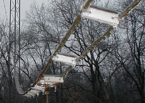
1. Significant QSY requires some knob twisting. Quick settings for QSY are achieved with a look-up table of known calibrations. Unlike coax, when the line ices up, the tuning changes significantly. Rain affects it less however, than the window-style balanced line. and icing happens maybe once per year in Kentucky.
2. The line must be kept well away from conductive and semiconductive materials to maintain balance. When running near conductors, twisting can help keep it balanced.
3. Pay attention to your matching network - this is really the only potentially significant source of loss.
It's not common, and I don't have it, but for absolutely optimal efficiency, a substantial radial or counterpoise ground system can be constructed under this antenna (and most other 40-160 meter antennas), further reducing resistive ground losses. The idea is for the ground under the antenna to reflect, rather than absorb (convert to heat ) RF in soil resistance..
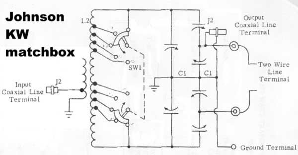
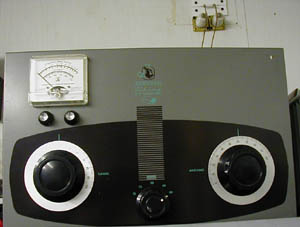
The Johnson kilowatt matchbox was made when this type of multiband antenna was very common. It's unique in that it uses no balun to convert a single ended network to balanced operation, as most modern units do. The performance of some ferrite core baluns deteriorates as the load substantially departs from the intended impedance - its not uncommon with this multiband antenna system to operate the line at 10:1 [or higher] SWR with very low losses, and a perfect match to the transmitter. From a flexibility, efficiency, and transmitter load impedance standpoint, this is the superior system.