Rumors of the AM mode of amateur operation having been fully supplanted by ssb may be exaggerated. Referred to as "phone" operation for many years, AM is the traditional voice mode, and still works great, particularly with older equipment. There remains much activity around 1.885, and 3.885 MHz. AM'ers tend to be more technical Hams - tinkerers, homebrewers, and radio parts packrats - keeping the true spirit of the origins of ham radio alive.
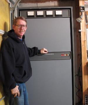
Old broadcast transmitters (at least the smaller ones) make great ham AM units, operating very conservatively with clean audio. I came by this still-installed but removed from service Gates, made about 1969, at a small AM station in Western Kentucky - WKDZ, and I owned it soon afterward for a reasonable trade with the station owner. My friend Roger Hall helped me move it, and about July of 2012 I began the restoration process - like many such units, maintenance toward the end of it's service life was somewhat neglected.
My first encounter with this ubiquitous model was actually it's father, the BC1T, at WDZ in 1977 relegated to standby, and later one at WTCJ. At one time this basic design was so common that it seemed most small AM stations had one - I'm not sure of the actual production runs, but I think a couple of thousand were made. The original brochure in pdf format is here.
Click each picture to enlarge
As I found it, it was obvious that it needed some tlc and a lot of elbow grease to turn it back into a reliable unit. The first job was disassembly and cleaning.
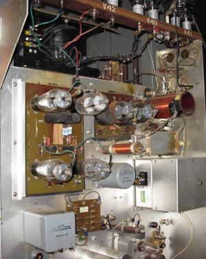
The wall-mounted components components were in pretty-good condition, but I wound up replacing the audio driver-related capacitors and a number of bypasses. The 807 rf driver tube shields originally made by Millen needed refinishing.
Gates stuck to the 833 triode design long after RCA, CCA, and McMartin were building similar transmitters with 4-400 tetrodes - probably because, after selling so many of a proven design, they saw no reason to change. If I recall, the subsequent model was the same as well, excepting a solid-state crystal oscillator assembly. After that model came the MW-1 - the world's first solid-state 1 kw broadcast transmitter.
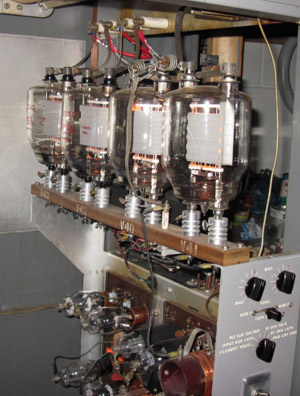
The cylindrical "sockets" for the filament connections were badly corroded. I turned them on a lathe while using a rotary wire brush, and re-tapped the setscrew holes.
The two RF 833s on the right turned out to be the only tubes that were usable after the restoration.
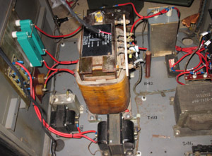
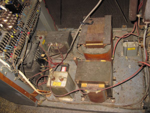
This was the first model to use modern solid-state rectifiers rather than tubes - but those early diodes were fragile compared to today's parts, so they were replaced. All of the high-voltage wire was old and brittle, just begging for disastrous arc-overs, so that was replaced.
One of the first jobs was to install casters on the bottom of the chassis to permit easy movement. Unfortunately, during the transition to vertical, a support line slipped, causing an unforeseen swing which badly gouged the original HV transformer. Fortunately I had another similar unit in my packrat area which I retrofitted without much trouble.
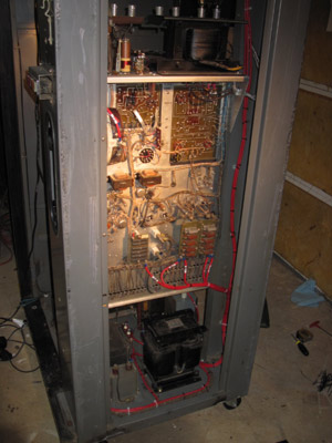
I made Delrin standoffs for holding the existing wiring harness away from chassis as much as possible to avoid future failures.
I encountered a few odd modifications which had to be undone, and a few failed connections. Unlike the earlier BC1T, this model featured a swing-out hinged chassis for much of the circuitry, but it is much easier to remove the right-side panel for better access.
I installed a new RF driver (807) plate relay which followed the HV contactor - normally the oscillator, buffer and driver come on with filament. I needed it to follow the HV so as not to operate without drive during periods of receive.
The output network was originally a PI-L-C-L with two of the coils being the front-panel rotary variables. Not needing 73+ dB harmonic attenuation, I converted to a PI-L by changing the two capacitors and removing the last LC.
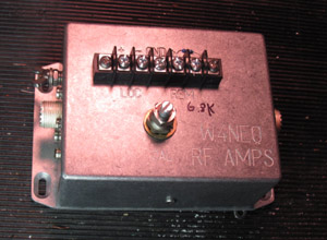
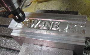
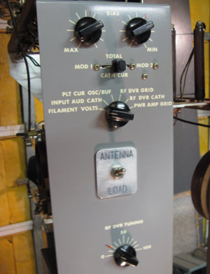
On the suggestion of Don, W4KYV, who converted his BC1T to 160 meters, I modified the oscillator stage by grounding the grid with a capacitor, and driving the cathode through a 1:4 torroidial unun. To ensure stability I ultimately used a 6 dB pad at the VFO input, which accepts 5 volts p-p for normal drive. The 12BY7A buffer stage required removing some turns from the plate tank coil, and replacing the parallel fixed capacitor with a variable to resonate.
I re-did the internal 50 ohm load with a relay - and installed a front-panel switch in a previously drilled "pre-sunrise power" hole.
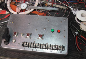
Late December, 2012 - the unit is finally operational on 160 meters, remotely controlled from the operating position.
73, Chris
Back to W4NEQ main page
